PCB Mechanical Fatigue Cycler
I designed and built a cyclical fatigue fixture using a crank-slide mechanism to diagnose and solve a reliability issue, within a timeline of 2 days
***Disclaimer: I’ve written this page purposefully vague to avoid revealing company hardware. I might update it at some point in the future, but since I am focusing on my design work, likely will not need to.
Our core product is a smart mattress topper, with temperature regulation and biometric sensing. During the development of a previous iteration of the product, we had a failure with a PCB used in biometric sensing that resulted in poor sensor signals. After inspection of the failed boards, we diagnosed the issue to be a mechanical failure from some sort of a 3-point bend loading scenario, and I was brought in to build a fixture to replicate the issue so that we could mitigate it.
The design requirements of the fixture were that it needed to flex the 1”×3” PCB boards up to 200N, at a rate of 1 cycle/s, and detect deterioration of the signals from the boards. Ideally the system would also be running within 2 days.
Because of the timeline, I went into the design trying to use parts that I knew we already had on-hand, or could get delivered next-day. I decided on a slider-crank mechanism to produce the reciprocal linear motion, using a large motor from a previous project that I knew could handle the loads by checking the torque spec against a simplified load calculation. I opted to control the force passively with springs, rather than actively using a force gauge in-line with the test head, simply because I didn’t have a workable force-gauge on hand to meet the timeline. See early concept work below, followed be detailed design.
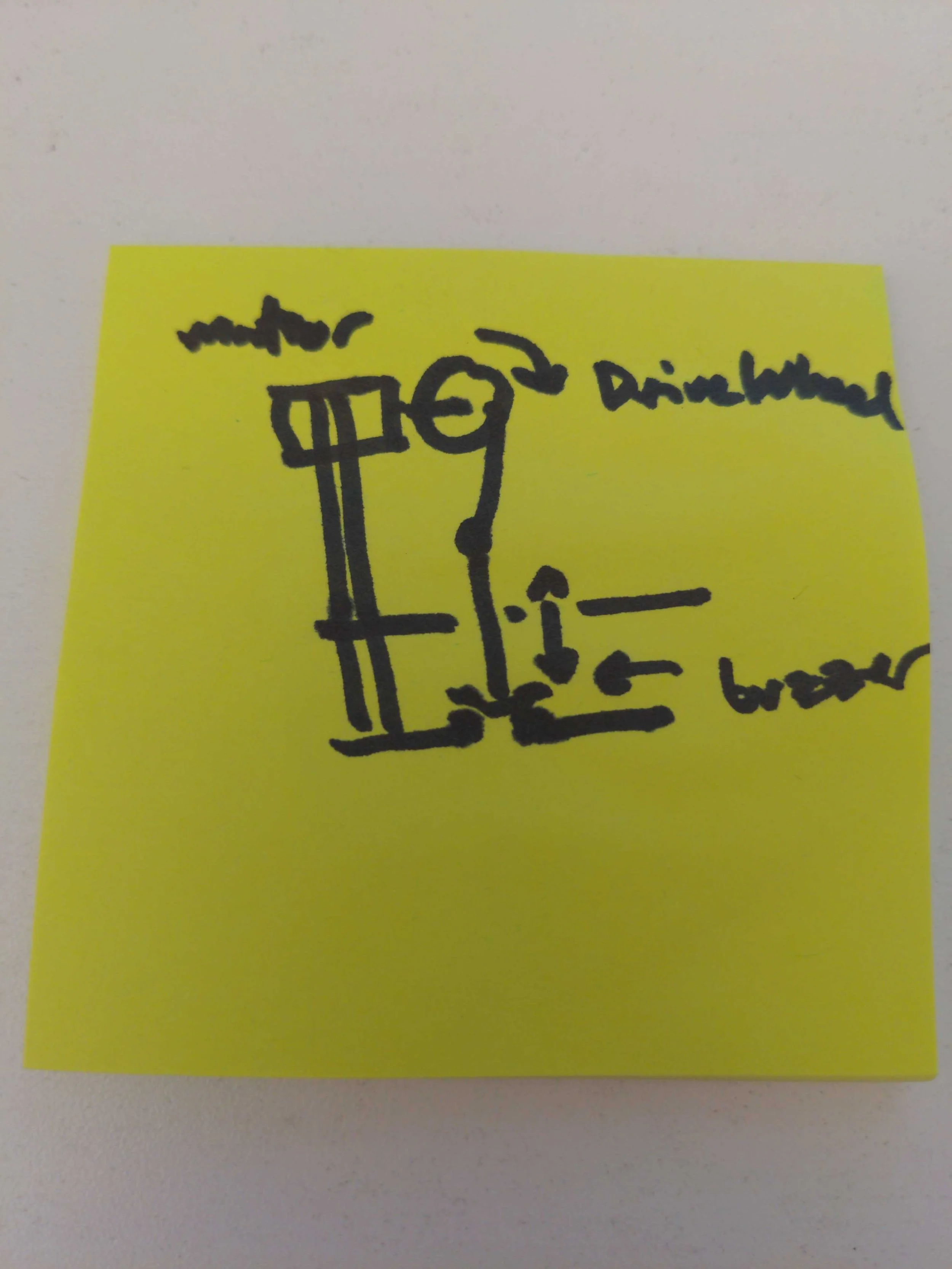
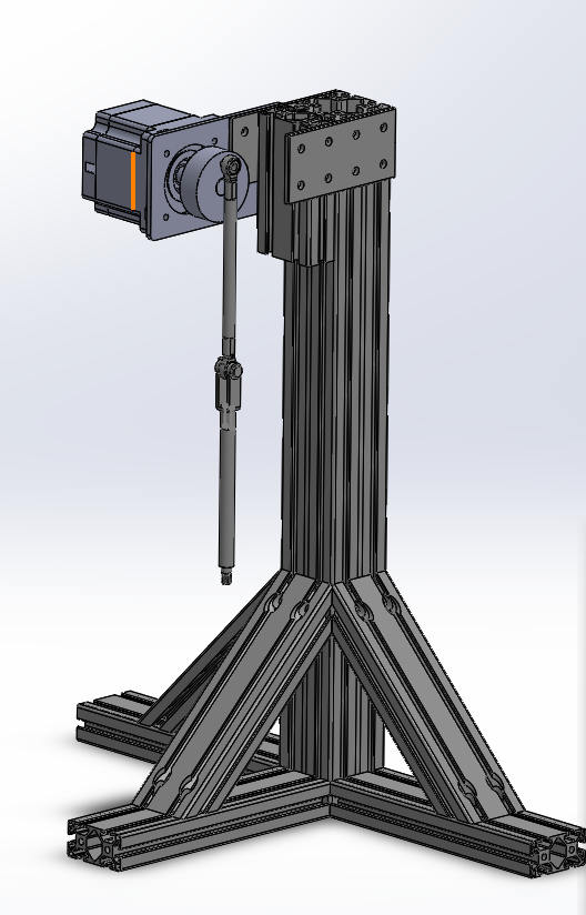
Early sketch of the design (left) and the rough CAD (right) I made right after I was asked to build the fixture. I used both to show the applicable teams where I was thinking of going. Once this was approved, I moved on to detailed design (below)
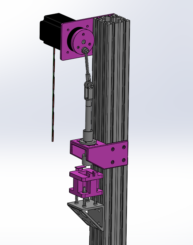
The structure is built around 8020 and the larger motor I had on-hand. Custom parts (shown pink) include aluminum mounting plate, drive wheel, linear bearing mount, and the spring stage. All parts for the drive linkage were delivered next-day from McMaster-Carr.
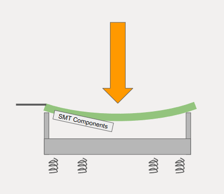
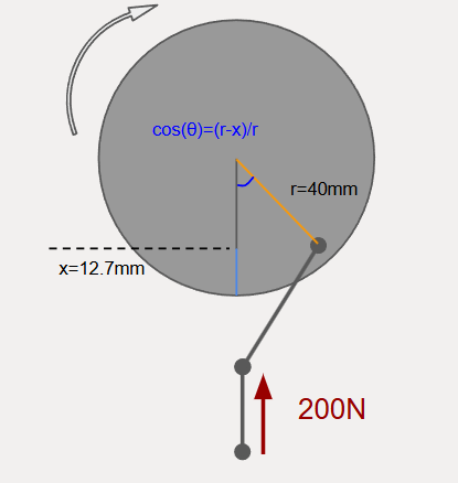
Spring stage concept (left) and the simplified load calc diagram (right). The spring stage allows the total force to be set by 4 springs in parallel, with the compression head contacting the PCB and displacing it and the stage down a known amount, with the force following F=kx. If the force needed to be changed, the springs simply needed to be swapped out for higher or lower k values. The load calcs were simplified to be over-conservative, and assumed the force going into the drive wheel was perfectly vertical.
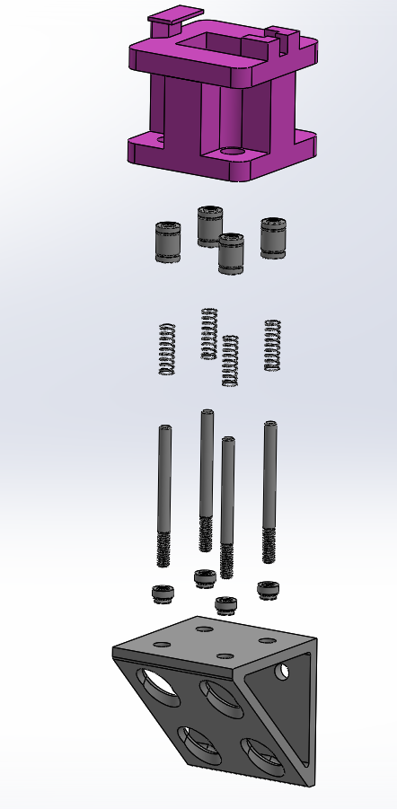
The spring stage (left) consisted of springs placed around linear rods, which slide through linear bearings in the stage so the force on the stage could translate directly to the springs, while the stage is constrained laterally.
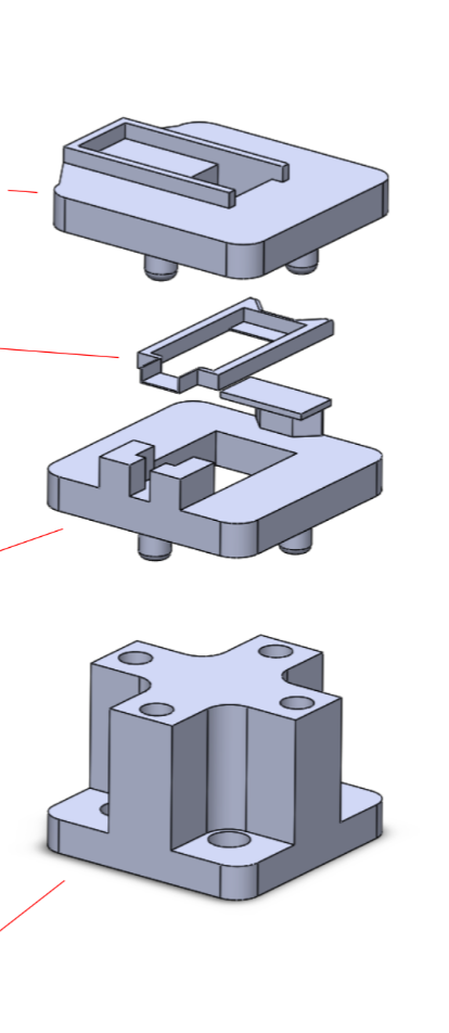
The stage itself (right) I designed to be modular, so that you could design custom holding fixtures to iterate on the geometry, position, and load condition of the PCB sample. The stage base is also used to datum against the fully extended compression head, and therefor set the the travel of the springs (and force from F=kx) via the height of the holding fixtures placed on top of it.
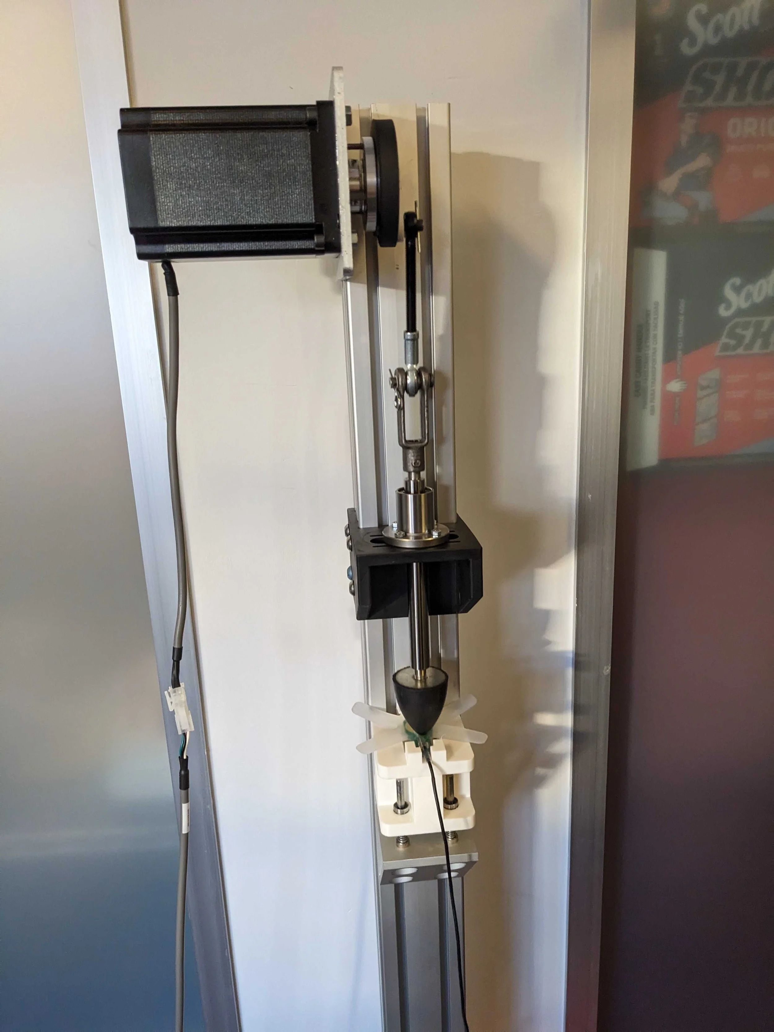
Ultimately I was able to develop this fixture and get it running within the 2 day timeline successfully, leaning on Claude AI to write the control scripts and integrate the motor control and sensor feedback into one program. After 2 weeks of regularly using the fixture, we were able to successfully reproduce the failures we were seeing and correct them, with the root cause being the combination of a process issue and mechanical loading. See below for a video of the functioning fixture, as well as some design mistakes and lessons that I learned from this process, which I will definitely keep in mind in future projects.
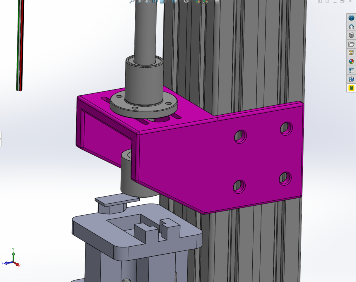
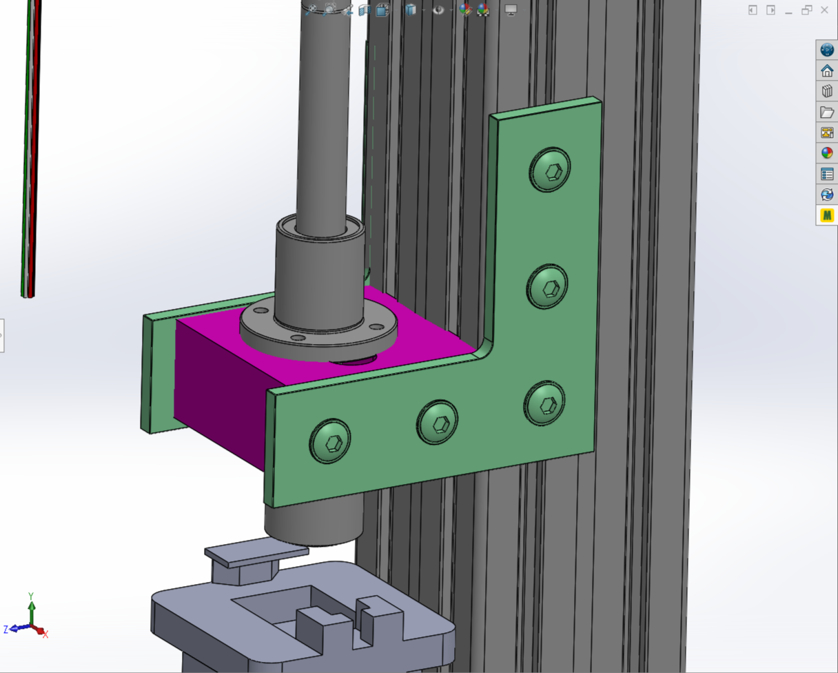
I needed to make this linear bearing mount (left) custom to adapt bearing that constraints the vertical linear rod directly to the 8020 post. It was SLA printed, and the loads and fatigue should not be an issue as there is no directly loading condition, however the part complexity is too high and doesn’t allow quick iterations. Instead, I should have better utilized off-the-shelf 8020 fasteners, changing the part geometry from a complex bracket to a simple block that could be easily machined or swapped if need be (right)
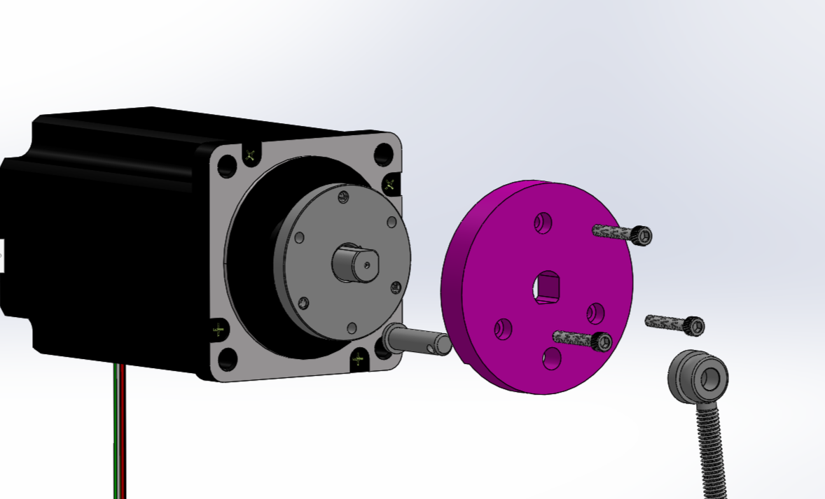
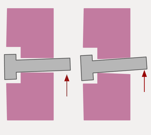
The custom drive wheel was needed to adapt the off-the-shelf shaft collar to the linear rod linkages. It was SLA printed, adequate for expected loads but without a bushing protecting the resin. After a week the clevis pin wore down the hole and added ~1mm of play to the stack, which significantly reduced fixture accuracy and required maintenance. In future iterations the stack will have an added bushing to protect against wear, or will swap to a ball-joint rod end to account for the motion